Understanding transformer rating plates is essential for anyone working with electrical power systems. These small metal plates contain vital technical information that helps engineers, electricians, and maintenance teams install, operate, and maintain transformers safely and effectively.
From voltage ratings and power capacity to impedance values, temperature limits, and cooling methods, the information displayed on a transformer rating plate provides a clear overview of how the transformer is designed to perform and the conditions it is built to operate under.
At first glance, transformer rating plates can seem complex. Filled with abbreviations, technical terms, and detailed specifications, it makes it difficult to interpret without the right background knowledge. Misunderstanding and not being able to read the transformer rating plates can lead to incorrect installation, operational problems, or equipment damage.
In this guide, we’ll break down the key information found on a transformer rating plate, explaining what each value means and why it matters. Whether you’re specifying new equipment, commissioning a transformer, or simply looking to build a better understanding, this guide will help you read and interpret transformer rating plates with confidence.
Transformer Rating Plates
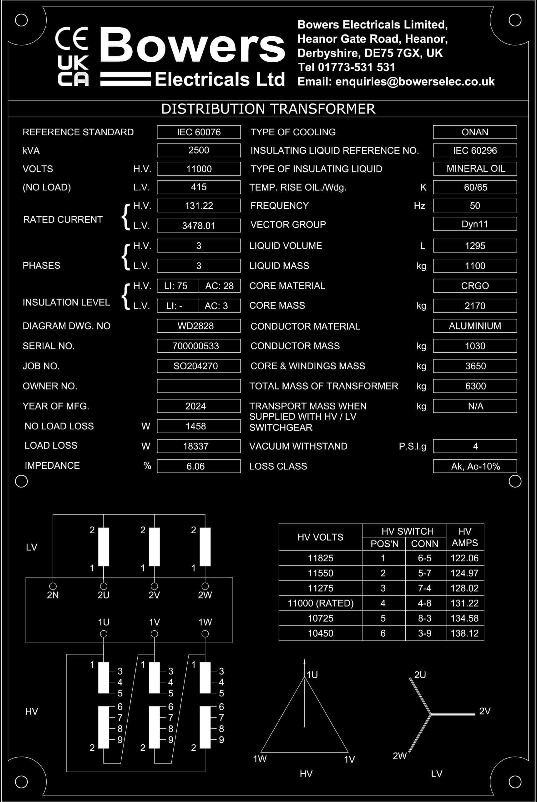
This is what a Bowers Transformer Rating Plate looks like.
The rating plate tells engineers and technicians exactly how the transformer is designed to perform, including its electrical ratings, configuration, and operating conditions. This ensures the transformer is used within its intended limits and connected correctly within an electrical system.
This is how it’s broken down and what each of the numbers and labels means.
Transformer Rating Plate Main Table
The main table on a transformer rating plate contains the core technical specifications that define how the transformer is designed to operate.
Reference Standard – This indicates the International Standard that the transformer is designed and manufactured to. By complying with these standards, it helps you, too, as you know that our products are safe and the best they can be for the environment.
kVA – The kVA rating of a transformer is its apparent power capacity—the maximum amount of electrical power the transformer can safely transfer continuously under its design conditions without exceeding its temperature limits. This value may be expressed in MVA for larger rated transformers. The selection of rating is typically based on the number of transformers being deployed to supply the connected load, taking into account any redundancy deployed.
Volts (HV & LV) – The voltage rating of primary and secondary voltage, noting that the secondary voltage is expressed at no load and will fall to a lower level when the transformer is supplying load due to the impedances of the transformer. Transformers are typically used to step up voltage levels to enable power to be transmitted over long distances efficiently, and then stepped down to a safer and more usable level that can be used in homes and businesses.
Rated Current (HV & LV) – Rated current on a transformer rating plate refers to the maximum continuous current that the transformer windings are designed to carry safely under normal operating conditions. This information is important to make sure that the electrical connections to the transformer are sized correctly.
Phases (HV & LV) – The phases label indicates how many alternating current (AC) phases the transformer is designed to operate with. This tells you whether the transformer is built for a single-phase system or, more typically, a three-phase electrical supply.
Insulation Level – Insulation level refers to the maximum electrical stress that the transformer’s insulation system can safely withstand without breaking down. The values refer to overvoltage levels that apply at nominal power frequency as well as due to impulse voltages that can be experienced due to power surges, lightning strikes, etc. The values specified are normally related to the operating voltages of the transformer, although higher values may need to be specified if the transformer is at a higher altitude, in an area that experiences high lightning activity, or if the transformer is connected to long lengths of overhead line.
Diagram DWG. No. (Drawing Number) – The diagram drawing number on a transformer rating plate refers to the unique reference number for the manufacturer’s technical drawings associated with that transformer.
Serial No. – The serial number on a transformer rating plate is a unique identification number assigned to that specific transformer by the manufacturer.
Job No. – As a customer, your order has a specific job number that is created by Bowers and is unique to you and your order. It makes communication open and easy.
Owner No. – The owner number is assigned by the company or organisation that owns the transformer (for example, a utility, industrial site, or infrastructure operator).
Year of MFG (Manufacture) – This shows the year in which the transformer was manufactured and tested.
No Load & Load Losses – Although transformers are highly efficient, they produce electrical losses which are characterised by two main features. No Load Losses (iron or core losses): These are the losses that apply when the transformer is energised but not supplying any load and comprise the energy needed to magnetise the core of the transformer and the heating effects of circulating currents within the core and windings. Load Losses (copper or winding losses): These are the losses that occur when the transformer is supplying a load and are primarily caused by the resistance of the winding material.
Impedance – This is one of the most important parameters in transformer specification. It determines how much current the transformer will feed into a downstream fault, but also how much the output voltage will drop between no load and full load.
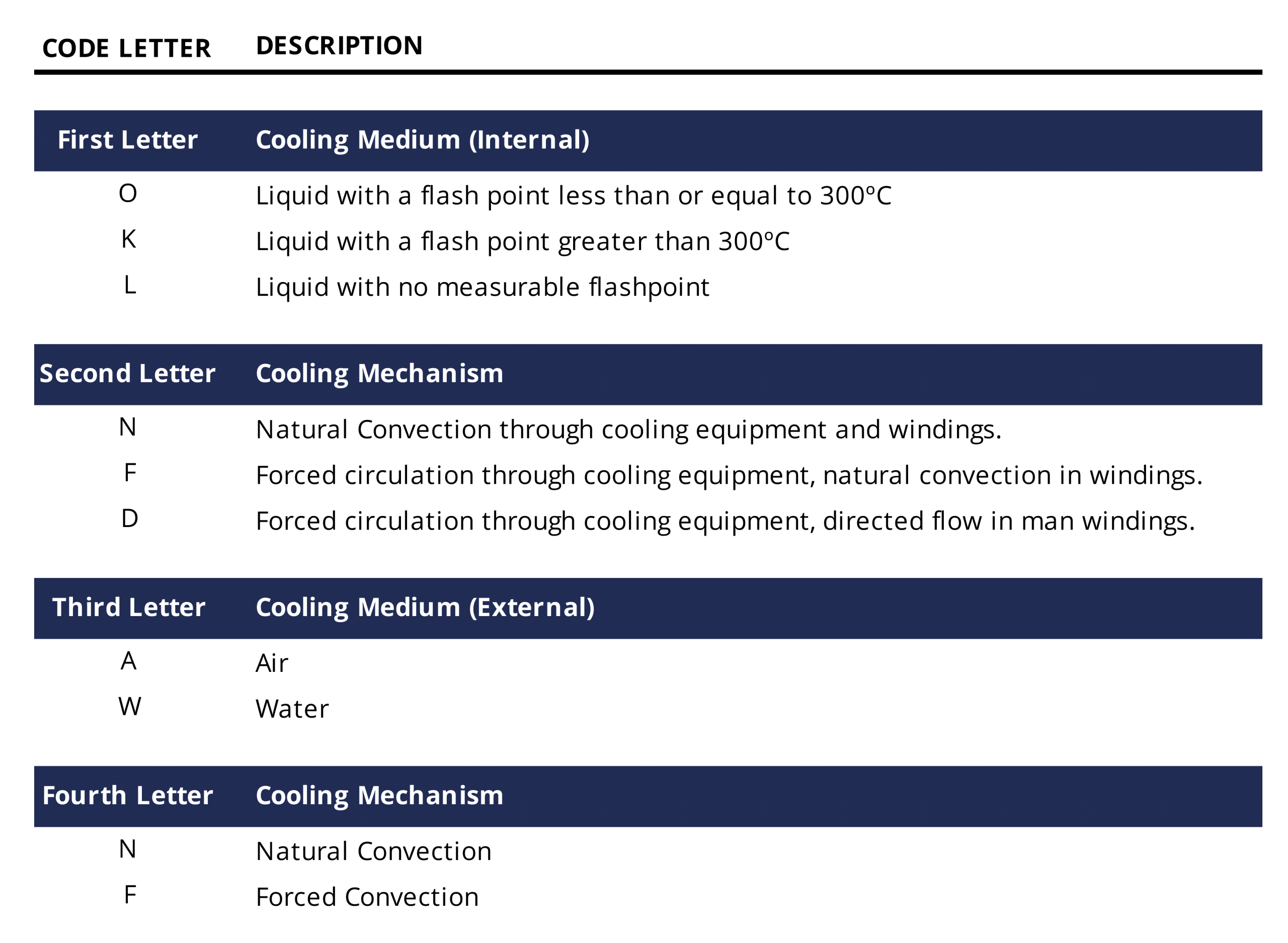
Type of Cooling – Heat is one of the leading causes of transformer failure, as it can lead to premature failure of the winding insulation. So it is easy to see why it is important to have cooling systems in place. The cooling classification of a transformer, expressed in letters, designates the type of cooling system used. The letter abbreviation system is as follows:
Insulating Liquid Reference No. – The insulating liquid reference number on a transformer rating plate refers to the standard or specification that the insulating liquid inside the transformer complies with.
Type of Insulating Liquid – The type of insulating liquid on a transformer rating plate refers to the specific kind of di-electric fluid used within the transformer tank for insulation and cooling.
Temp. Rise Oil/Wdg. – This refers to the maximum temperature rise of the insulating oil and windings above the ambient temperature during normal operation. Transformers naturally generate heat when carrying an electrical load. The temperature rise value shows how much hotter the oil and windings are allowed to get compared to the surrounding air when the transformer is operating at its rated load. On the rating plate, it is shown in K, which refers to Kelvin, which is a unit used to measure temperature difference rather than absolute temperature.
Frequency – The frequency on a transformer rating plate tells you how many electrical cycles per second the transformer is designed to work with, and Hz (Hertz) is the unit used to measure those cycles.
Vector Group – A Vector Group categorises the winding configuration used in three-phase transformers. The first symbol is for high voltage and is always in a capital letter, the second symbol is for low voltage and is always small letters, and the third symbol is a number representing phase displacement.
Liquid Volume & Liquid Mass – This shows the total quantity of insulating liquid contained inside the transformer; the measurement is shown in litres (L). The liquid mass refers to the total weight of the insulating liquid contained inside the transformer, measured in kilograms (kg).
Core Material& Core Mass– Core material refers to the type of magnetic material used to construct the transformer’s core. The core is the central part of a transformer that carries the magnetic flux between the primary and secondary windings, allowing electrical energy to transfer from one circuit to another through electromagnetic induction. The core mass on a transformer rating plate refers to the total weight of the transformer’s magnetic core; the measurement is shown in kilograms (kg).
Conductor Material & Conductor Mass – Conductor material states the type of metal used to make the transformer windings. The windings are the coils that carry electrical current in the primary and secondary circuits, creating the magnetic field that allows the transformer to transfer energy between voltage levels. Conductor mass on a transformer rating plate refers to the total weight of the conductor material used in the transformer windings, measured in kilograms (kg).
Core & Windings Mass & Total Mass of Transformer – These ones are pretty self-explanatory. Core and windings mass refers to the combined weight of the transformer’s magnetic core and its electrical windings, measured in kilograms (kg). The total mass of the transformer shows the overall weight of the complete transformer when fully assembled, also measured in kilograms (kg).
Transport Mass When Supplied with HV / LV Switchgear – This refers to the total weight of the transformer during transport when it is supplied together with its associated high-voltage (HV) and low-voltage (LV) switchgear. Switchgear includes the electrical switching and protection equipment that connects the transformer to the power system, such as circuit breakers, isolators, and protection devices. This value helps with transport planning, lifting requirements, and delivery logistics. If the rating plate shows N/A (Not Applicable) (like in this case), it usually means the transformer is not supplied with HV or LV switchgear as part of the same unit.
Vacuum Withstand – This refers to the ability of the transformer tank to safely withstand internal vacuum pressure without being damaged or deformed. During certain maintenance or manufacturing processes, air and moisture are removed from the transformer tank by creating a vacuum inside it.
Loss Class – This refers to the efficiency category of the transformer based on the amount of electrical energy it loses during operation.
These are all the contents of the main rating plate table. Together, these values provide a complete technical overview of the transformer and its operating limits. The information on the rating plate allows engineers, installers, and maintenance teams to quickly identify the transformer’s key electrical characteristics, construction details, and physical properties.
Rating Plate Diagrams and Tap Changer Table
The rating plate diagrams and tap changer tables provide a quick visual reference for a transformer’s electrical connections and voltage adjustment options. They help operators understand how to configure the transformer safely and efficiently, ensuring optimal performance under varying load conditions.
Winding / Terminal Connection Diagram(Diagram 1) – This diagram shows how the transformer windings and terminals are arranged internally. It shows the location of the terminals, the winding layout and the tap positions for voltage adjustment.
Tap Changer Table – This table shows how the HV tap changer adjusts the transformer voltage. Each tap position changes the number of turns used in the HV winding. Power networks rarely stay exactly at the rated voltage. The tap changer allows engineers to fine-tune the transformer voltage to keep the LV output correct. (NB: Off-circuit operation is typical, so the transformer must not be energised when changing tap position.)
Vector Group Diagram (Diagram 2) – This diagram shows the phase relationship between HV and LV windings. It shows the vector group/connection type.
Alongside the main rating plate table, the diagrams and tap position table provide additional technical information about the transformer’s internal connections and voltage adjustment capabilities.
The winding diagrams illustrate how the high-voltage (HV) and low-voltage (LV) windings are arranged and connected, while the vector diagram shows the phase relationship between them. The tap changer table details the different switch positions available to adjust the transformer’s high-voltage input, allowing engineers to fine-tune the voltage to suit variations in the electrical network.
Together, these diagrams and tables help engineers understand how the transformer is configured, how it should be connected on site, and how its operating voltage can be safely adjusted when required.
Conclusion
Understanding the information shown on a transformer rating plate is essential for anyone involved in the installation, operation, or maintenance of electrical equipment.
While the values, diagrams, and technical references may appear complex at first, each element serves a specific purpose in describing the transformer’s capabilities, configuration, and operating limits. From the main specification table to the winding diagrams and tap changer information, the rating plate provides a complete snapshot of the transformer’s design and performance.
By becoming familiar with how to read and interpret this information, engineers and technicians can ensure transformers are connected correctly, operated within their rated limits, and maintained safely throughout their service life.
In many ways, the rating plate acts as the transformer’s technical identity card, which provides all the key details needed to understand and work with the equipment confidently.